|
 Momentum resolution. Momentum resolution.
The core business of the tracker is the precise determination of the three-momentum of charged particles. While the exact added value of a superb momentum resolution can only be determined by establishing its impact on the physics programme, it is clear that the tracker design is largely driven by the transverse momentum resolution requirement. In this section, the impact of several parameters of the detector design on the momentum resolution is evaluated.
Setup
As reference point for the momentum resolution, a geometry is created with the following baseline parameters.
| detector | resolution R &phi (&mu m) | resolution R/z (&mu m) | material (% X 0) |
| VXD | 5 | 5 | 0.12/layer |
| FTD1-3 | 10 | 50 | 1.2/layer |
| FTD4-7 | 10 | 1000 | 0.8/layer |
| TPC | 120 | 300 | 1 (field cage) |
This geometry represents a conservative scenario: a detector with these specification can be built with existing technology. The effect of more challenging detector specifications on the momentum resolution is the discussed later on in this section.
The momentum resolution for tracks of varying momentum is determined by fitting the measurements of the detectors with the Kalman Filter track fitter/smoother described in some details in the section on Tools.
Angular dependence
In typical collider detectors the (transverse) momentum resolution depends quite strongly on the polar angle. There are two main reasons for this dependence. The transverse momentum resolution degrades in the forward region as a result of the non-optimal orientation of the magnetic field. This is true even if the tracking volume is instrumented in an exactly uniform way. The second reason is that typical detectors are far from uniformly instrumented. The number and type of detectors - and therefore the amount of material and the number, lever arm and resolution of available measurements - varies with polar angle.
Even in the relatively uniform forward tracking regions of the four concepts, several cases must be distinguished. In the following, these three benchmark points corresponding to the nominal LDC layout are used:
- 10 degrees: the track is detected in all seven forward disks and by no other tracker devices.
- 15 degrees: the track is detected in two VXD layers and the first six Forward Tracking Disks.
- 20 degrees: the track is detected in three VXD layers, the first five Forward Tracking Disks and traverses a corner of the TPC.
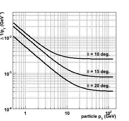
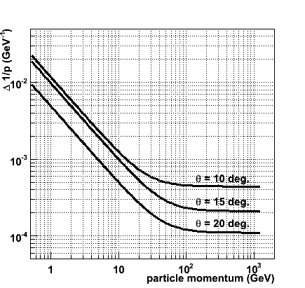
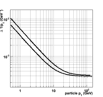
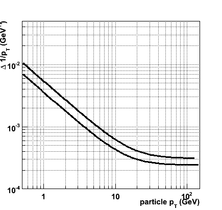
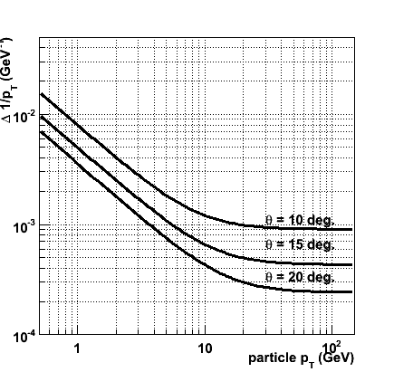
The results for the three polar angles are shown in the figures below. In the leftmost figure the error on 1/pT is plotted as a function of the true transverse momentum, in the rightmost figure &Delta( 1/p ) is plotted as a function of the true momentum (note the difference in axis range of the two figures). In both cases, the uppermost curve represents the result at a polar angle of 10 degrees, and the middle and lower curve correspond to 15 and 20 degrees, respectively.
Dependence on detector parameters
In this section, a series of challenges is defined and their effect on the transverse momentum resolution is evaluated. The challenges are optimistic (but certainly not impossible) variations of a single detector parameters with respect to the conservative baseline specifications:
- A factor two improved R &phi resolution ( 5 &mu m) of FTD disk 1 to 3
- A factor two improved R &phi resolution ( 5 &mu m) of FTD disk 4 to 7
- A factor ten (!) reduced material budget ( 1.2 &permil X 0 /layer)for FTD disk 1 to 3
- A factor two reduced material budget ( 4 &permil X 0 /layer)for FTD disk 4 to 7
While there is necesarily a degree of arbitrariness in these variations, they are inspired by technology options (see the section on detector technologies).
The first three and last four disks are considered separately for a number of reasons. To cope with the higher density the first three disks are foreseen to be equipped with high granularity (pixel) detector, while for the outer four more traditional silicon micro-strip technology is expected to be sufficient. Moreover, the innermost three disks correspond to a relatively small area (roughly half a square meter in the nominal LDC detector, while the outer four disks correspond to nearly two square meters). Thus, more challenging technologies may be employed on a sub-set of disks.
The challenges in terms of material budget for the inner and outer disks are chosen in line with the above discussion. The factor ten for the inner disks corresponds to the replacement of hybrid pixel technology with state-of-the-art active pixel detectors like those employed in the Vertex Detector. For the outer four disks the reduction by a factor of two might be achieved by moving to double-sided micro-strip technology.
The listed challenges represent a small subset of detector parameters. All other parameters were considered in a first scan of parameters, but were discarded for one of two reasons. For some parameters, the sensitivity of the momentum resolution is either very small or inexistent. This is the case of the resolution of the measurement in the non-bending plane (z in the cylindrical central detectors, R in the FTD). Its value has no impact on the momentum resolution: a trivial statement when considering the transverse momentum, but found to hold also for the magnitude of the three-momentum) and for the number of layers. Other parameters are so constrained by the overall design that only insignificant variations are possible (the length of the forward tracker).
20 degrees
In the case of a 20 degree polar angle, the corner of the TPC contributes significantly to the momentum resolution. Assuming the resolutions listed above and a field cage material of 1 % X0 the TPC measurements lead to a factor two improvement of the momentum resolution with respect to the silicon-only case. The importance of this contribution depends strongly on the assumption for the material in the inner field cage: for a 10 % X0 field cage the performance with or without TPC measurement is virtually identical.
The performance of the baseline configuration may be parameterized as follows:
&Delta ( 1/pT ) = 3.1 × 10 -4 &oplus 5.4 × 10⁻³ / pT, or in terms of momentum
&Delta ( 1/|p| ) = 1.1 × 10 -4 &oplus 4.9 × 10 -3 / p
The sensitivity to the space point resolution of the silicon tracker sub-systems is quite weak. Improving all silicon detector resolutions by a factor 2 (i.e. a VXD resolution of 2.5 &mu m, and FTD resolution of 5 &mu m) leads to a modest improval of the constant term to 2.7 × 10⁻⁴ (an improvement of 13 %) and no appreciable change in the multiple scattering term. If the resolutions are changed individually for the VXD, the first three FTD disks and the final FTD disks, the improvement in the momentum resolution is greatest when the resolution of the first three FTD disks is changed.
As expected, a change of the FTD material budget is quite effective to improve the multiple scattering term. In the figure the transverse momentum resolution of the baseline setup is compared to that of a much more agressive set of assumptions on the material budget. In this alternative setup the first three FTD disks only contribute 1.2 &permil of a radiation length to the material budget. The final four disks are assumed to contribute only 4 &permil X0.
There is a clear improvement for transverse momenta up to approximately 20 GeV (i.e. a momentum of nearly 60 GeV), where multiple scattering dominates the resolution. Quantitatively, the multiple scattering term of the pT resolution parameterization has improved from the 5.4 × 10⁻³ to 3.7 × 10⁻³ (an improvement with respect to the baseline of 32 %). The lion's share of the improvement is due to the reduced material in the first three disks (just this change gives a multiple scattering term of 4.0 × 10⁻³.
The combintation of the challenging spatial resolution scenario and the aggressive material budget assumption leads to a significant improvement of the overall transverse momentum performance:
&Delta ( 1/pT ) = 2.4 × 10⁻⁴ &oplus 3.6 × 10⁻³ / pT
&Delta ( 1/|p| ) = 0.8 × 10⁻⁴ &oplus 3.5 × 10⁻³ / p
The &Delta ( 1/pT ) vs. pT curves for nominal (upper curve) and challenging (lower curve) scenarios are shown in the figure.
15 degrees
The momentum resolution of the baseline detector for a polar angle of 15 degrees, is parameterized as:
&Delta ( 1/pT ) = 7.7 × 10⁻⁴ &oplus 1.0 × 10⁻² / pT
&Delta ( 1/|p| ) = 2.1 × 10⁻⁴ &oplus 1.0 × 10⁻³ / p
As in the case of a 20 degree angle, variations of the space point resolution of the silicon tracker sub-systems have a moderate effect on the resolution. Multiplying the VXD resolution by 1/2 (2) leads to less than 10 % improvement (deterioration) of the constant term. The effect of a factor 2 improved resolution in the first three FTD disks is somewhat larger; the constant term in the transverse momentum resolution decreases to 6.6 × 10⁻⁴ (an improvement of 11 % with respect to the baseline).
And, as before, the material of the first three FTD disks is found to have a large effect on the multiple scattering term.
&Delta ( 1/pT ) = 7.6 × 10⁻⁴ &oplus 0.61 × 10⁻² / pT
&Delta ( 1/|p| ) = 2.0 × 10⁻⁴ &oplus 0.6 × 10⁻² / p
A reduction in the material in the last four FTD disks also has a very significant effect:
&Delta ( 1/pT ) = 7.6 × 10⁻⁴ &oplus 0.81 × 10⁻² / pT, or in terms of momentum
&Delta ( 1/|p| ) = 2.0 × 10⁻⁴ &oplus 0.80 × 10⁻² / p
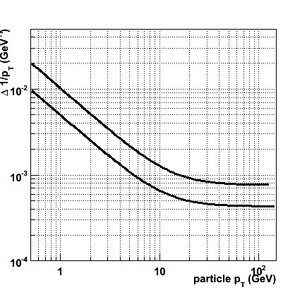
The combination of all challenges, i.e. achieving a factor 10 in material for the first 3 FTD disks, a factor 2 in material for the last 4 FTD disks and a factor 2 in resolution for all FTD R &phi measurements, yields a resolution of:
&Delta ( 1/pT ) = 4.1 × 10⁻⁴ &oplus 0.49 × 10⁻² / pT, or in terms of momentum
&Delta ( 1/|p| ) = 1.1 × 10⁻⁴ &oplus 0.47 × 10⁻² / p
The &Delta ( 1/pT ) vs. pT curves for nominal (upper curve) and challenging (lower curve) scenarios are shown in the figure.
10 degrees
For the smallest polar angle under consideration, the resolution of the nominal setup may be expressed as follows:
&Delta ( 1/pT ) = 1.8 × 10⁻³ &oplus 1.3 × 10⁻²/ pT
&Delta ( 1/|p| ) = 1.8 × 10⁻⁴ &oplus 1.2 × 10⁻²/ p
In this case, the variations in resolution are relatively effective. A factor two improved resolution in the first three disks yields a constant term of 1.4 × 10⁻³. The same improvement in the last four disks even yields 1.1 × 10⁻³. When the whole FTD can provide a 5 &mu m space point resolution, the constant term in the pT resolution goes down to 0.9 × 10⁻³.
The material budget of the first 3 FTD disks has less effect than for the larger angles. A factor 10 reduction of the material leads to a modest improvement of the multiple scattering term to 1.1 × 10⁻². The weight of the the material in the last four disks is slightly larger: a factor 2 reduction of the material leads to 0.95 × 10⁻². Reducing both leads to multiple scattering term of 0.82 × 10⁻² (a 35 % improvement).
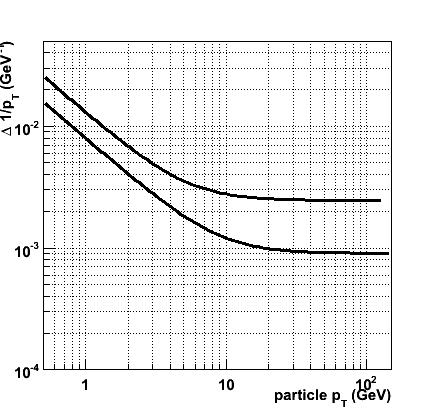
The full set of measures to improve the resolution (factor 10 material in FTD1-3, factor2 in FTD4-7, factor 2 improved resolution in the whole FTD) yiels the following resolution:
&Delta ( 1/pT ) = 0.91 × 10⁻³ &oplus 0.79 × 10⁻²/ pT
&Delta ( 1/|p| ) = 1.6 × 10⁻⁴ &oplus 0.75 × 10⁻²/ p
The &Delta 1/pT vs. pT curves for nominal (upper curve) and challenging (lower curve) scenarios are shown in the figure.
Discussion
In this section, the transverse momentum measurement performance of a forward tracker that fits the geometry of the LDC Forward Tracking Disks has been evaluated. For conservative assumptions on the space point resolution (10 &mu m in the R &phi measurment) and the material budget, the transverse momentum resolution versus transverse momentum for three polar angles is shown in the leftmost figure below.
Then, an alternative detector has been defined. The tracker disks in this scenario - of identical geometry - should provide a factor two better resolution (i.e. 5 &mu m) in the R &phi measurement. Moreover, the material budget is tighter by a factor 10 for the innermost three disks and a factor two for the outer four disks. While these specifications are certainly challenging, they are in reach of existing detector technology (that, admittedly has never been applied at such a scale).
The momentum resolution of the more challenging detector is shown in the rightmost figure below. The overall performance improves by nearly a factor 2 with respect to the conservative detector. This improvement is consistently achieved for the different polar angles considered and for momenta ranging from well below a GeV to beyond 100 GeV.
Home
Next Article
|