Tilecal Read-Out Driver
Introduction
This page contains the information regarding hardware,
firmware and software designs for the ROD development at Valencia.
Latest documentation and code are provided for this purpose.
General overview
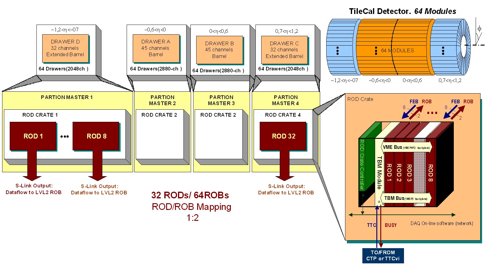
The Read Out Driver (ROD) is the intermediate link
of the chain between the front-end electronics and the general data
acquisition system of the ATLAS detector (TDAQ), see Figure
1. It represents the backend electronics of the Hadronic Tile
Calorimeter.
The Tilecal ROD has to read and process data from 9856 channels
each 10µs and it must be able to work in real time. The data
gathered from these channels are digitized and transmitted to RODs
with high-speed optical links. There are 256 digital optical links
(1 per FEB electronics drawer) that the ROD should be able to manage
and process at Level 1 trigger rate (100 kHz) and send to the Read
Out System (ROS) which is the next step in the ATLAS DAQ chain.
At this stage a second trigger decision (Level 2 trigger ~1 kHz)
will allow data to go to next step using algorithms based in Regions
of Interest (ROI). Data passing the Level 3 trigger (~100Hz) will
finally be stored in tapes for offline analysis. See the numbers
in Table 1.
Figure 1: Tilecal Detector partitions and readout
|
|
Number of Channels
|
9856 |
|
Number of input links (optical fiber)
|
256 |
|
Number of channels per drawer (EB)
|
32 |
|
Number of channels per drawer (CB)
|
45 |
|
Input event size per FEB (7 samples)
|
0,43 Kbytes |
|
Input Data Bandwidth @ 100kHz Lvl1 ATLAS
rate
|
14,03 Gbytes/sec |
|
Number of Drawers (FEB) per ROD module
|
8 |
|
Number of RODs
|
32 |
|
Number of Read Our Links (ROL ROD ROB
mapping 4:1)
|
64 |
|
Output Data Bandwidth @ 100kHz Lvl1
ATLAS rate
|
6,70 Gbytes/sec |
|
Typical output event size per ROD link
(4 to 1 I/O mapping)
|
1,10 Kbytes |
|
Total processing power needed
|
68992 MIPs |
Table 1: RoD facts
|
Summary of ROD basic functionalities:
- ROD Organization: The ROD modules are VME 9U modules controlled
by a rod controller (VME SBC computer) plus other trigger modules
(TBM) mounted in a 9U VME ROD Crate.
- DATA PROCESSING: Raw Data gathering from first level de-randomizers
at the L1A event rate 100 kHz. To provide energy, timing and pile
up estimation (chi2) to the next level by optimal filtering. Keep
the possibly to pass raw data without processing when it be advisable
(pile-up, high energy events).
- TRIGGER: TTC signals will be present (latency ~2us after L1A)
at each module providing ROD L1ID, ROD BCID and Ttype (trigger
type).
- ERROR DETECTION: These are synchronism Trigger Tasks. The ROD
must check that the owner BCID and L1ID numbers match with the
ones received from the FE. If a mismatch is detected, an error
flag must be set with some error code.
- DATA LINKS: Event data must be sent to ROB through the standard
ATLAS readout links and standard DAQ-1 data format at the L1A
event rate (100 kHz).
- BUSY GENERATION: Provide a ROD busy signal in order to stop
L1A generation. A global OR of the RODs busy per sub-detector
has to be provided to the CTP.
- LOCAL MONITORING: VME access of the data during a run without
introducing dead-time or additional latency in the main DAQ data.
Each ROD motherboard is VME slaves commanded by the ROD Controller
(VME SBC).
ROD design tasks developed at Valencia lab
|
Production
|
|
|