|
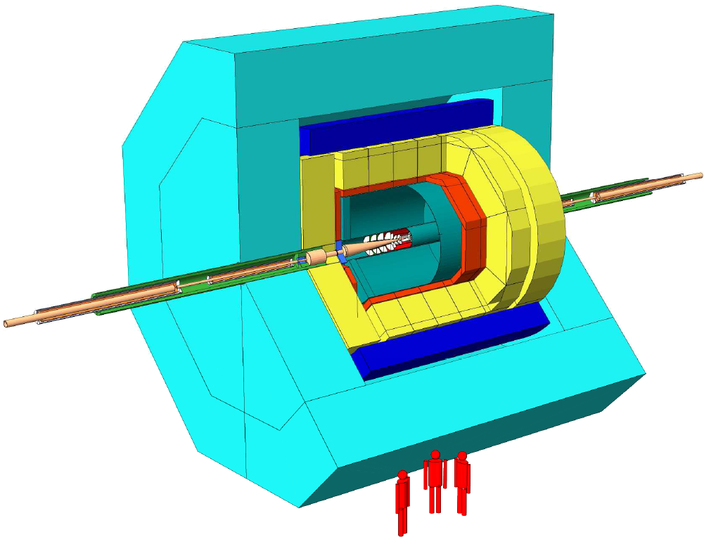
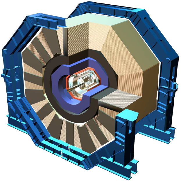
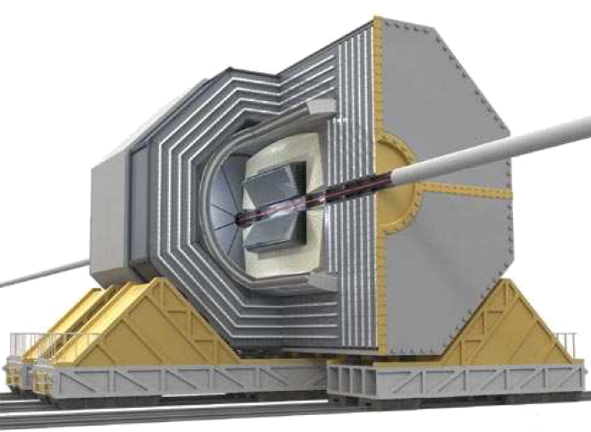
 Overall Detector Layout. Overall Detector Layout.
The tracker clearly does not stand alone. There is a strong interplay with the different detector sub-systems. Therefore, the scope of any detector design optimization cannot be limited to separate sub-systems: these studies necesarily take into account the overall system. In this section the reader is reminded of the essential parameters of four detector concepts. The tracker layout of the LDC/GLD concept - the framework of much of the study - is presented in some detail.
Detailed information is available through the following links.
Global layout
Two key parameter in the tracker design are the magnetic field and the lever arm. The two are tightly coupled: a given choice for the magnetic field strength conditions the size of the detector as the cost of the solenoid - and of the calorimeter - are the two principal cost drivers. The four concepts span a large range of possibilities from the small field-large lever arm of the GLD through the intermediate LDC to the compact high-field SiD concept.
| Concept | magnetic field | tracker outer radius | tracker half-length |
| SiD | 5 Tesla | 125 cm | 169 cm |
| LDC | 4 Tesla | 158 cm | 216 cm |
| GLD | 3 Tesla | 205 cm | 230 cm |
The lever arm for forward tracking is determined by the length of the tracking volume, rather than by the radius. As the aspect ratios of the trackers in the different concepts may vary considerably (from 0.72 for SiD and LDC to 0.89 for GLD) the tracker half-length is also given in the table. The half-lengths of the tracker concepts are given in the table.
Tracker concept
The four concepts have quite differing approaches to central tracking. In GLD and LDC, the central tracking volume is occupied by a large gaseous detector (a Time Projection Chamber). In the Silicon Detector Concept a 5-layer silicon (micro-strip detector) tracker is foreseen. In the 4th concept several possibilities are left open, among which a gaseous cluster counting chamber.
The choice of the central tracking technology has enormous implications on the overall detector design.
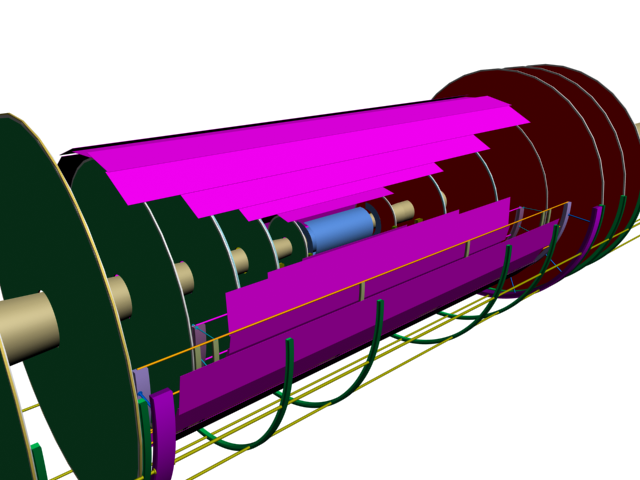
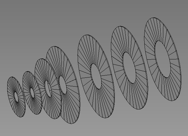
In the forward and backward regions of the four tracker concepts, the proposed solutions are far more uniform than in the central region. All concepts rely on silicon technology: the proposed detectors are a combination of silicon pixel and silicon micro-strip detectors. In the figure on the left the silicon detectors for inner central and forward tracking in the GLD concept are shown. The vertex detector (in blue) is complemented by four central silicon barrel layers and seven forward tracking disks on each side.
The "gaseous" tracking concepts involve a quite extensive silicon tracking system. The combination of gaseous and solid tracking detectors leads to a complex transition region. In the figure below the number of hits in the central and forward subsystems of the LDC tracker are represented as a function of polar anglewith respect to the beam axis. The results correspond to a sample of tracks reconstructed in fully simulated tt events using the FullLDCTracking algorithm. A minimum momentum of 1 GeV is required, but otherwise all tracks are accepted.
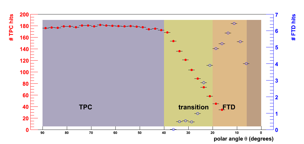
The red points, referred to the left-most vertical scale, mark the number of TPC hits (i.e. the number of readout rings that contain a signal). The blue points, referred to the rightmost scale, correspond to the number of FTD hits. Troughout the central region (&theta < 50 degrees) the average number of TPC hits per track is constant and approaches the number of readout rings (180). The transition region spans from 50 to 70 degrees; in this region the charged particles leave the TPC through the end-plate. The number of read-out rings decreases as the polar angle becomes smaller. The on-set of the FTD acceptance is visible in the same range. Finally, below &theta = 20 degrees the Forward Tracking Disks dominate the track measurement.
VXD-tracker interplay
There is a particularly strong interplay between the vertex detector and the tracker. Indeed, the naming is somewhat arbitrary: it is often hard to draw a precise line that indicates where vertexing stops and tracking begins. The 5-6 layer vertex detectors proposed for the ILC will turn out to be crucial to resolve ambiguities in pattern recognition.
The angular coverage of the vertex detector is an important parameter for the requirements in the very forward region. The coverage depends critically on the choice of the magnetic field strength. A higher magnetic field leads to a significant reduction of the pair background level and thus allows to reduce the inner radius of the vertex detector and/or to extend its half-length.
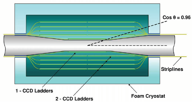
The four concepts have differing views on the vertex detector layout. In the GLD and LDC designs a "long barrel" vertex detector geometry is foreseen, while SiD and 4th prefer a "barrel + end-cap" type of detector. Specific requirement derive from the need to reconstruct tracks (and vertices) at very small polar angle ( < 18 degrees ) in detector concepts like LDC and GLD where the vertex detector has the "long barrel" geometry. The drawings for two examples are shown in the figure below.
 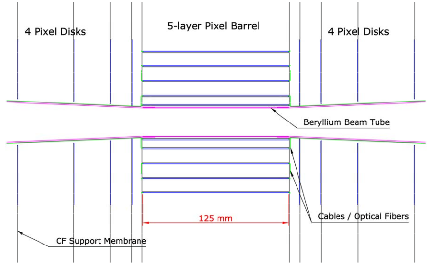
The angular coverage of the different vertex detector designs:
- for the SiD vertex detector (in a 5 Tesla field) the angular coverage of the 5th central barrel layers reaches 43 degrees for the 5th layer. Five-space-point coverage down to 12.5 degrees is provided by the end-caps. Tracks down to 8.5 degrees meet at least 3 VXD layers.
- for the vertex detector of the LDC (in a 4 Tesla field) the barrel layers provide five space point down to an angle of 25.8 degrees, three-point coverage down to 18.5 degrees. A single layer is traversed for tracks down to 12 degrees.
- for GLD the vertex detector barrels (in a 3 Tesla field) provides 6-point coverage down to 26 degrees (cos &theta = 0.9), and 4-point coverage down to 18 degrees (cos &theta=0.95). A disk provides an extra couple of space point down to 18 degrees. For smaller angles the vertex detector provides essentially no coverage.
Home
Next article
|