|
ILD silicon tracker layout
This page provides reference information on the layout of the silicon tracker elements in the Large Detector Concept (LDC). The implementation of the LDC layout in the Mokka simulation framework is documented.
Currently, LDC is merging with GLD to form a single detector concept known as International Large Detector (ILD). While the two detector concepts are certainly compatible, many differences exist in the details. With the aim of helping in the convergence of the two concepts, differences in the silicon tracker elements of both concepts are highlighted. This page also contains some notes about what physics channels are most likely to be useful in benchmarking different aspects of the detector performance.
After a brief introduction of the geometry description in the Mokka simulation framework, the different sub-systems are discussed in detail.
Links
The reference source for the LDC layout is a set of engineering drawings by Henri Videau. In some cases, these drawings represent important modifications with respect to the layout contained in the LDC Detector Outline Document.
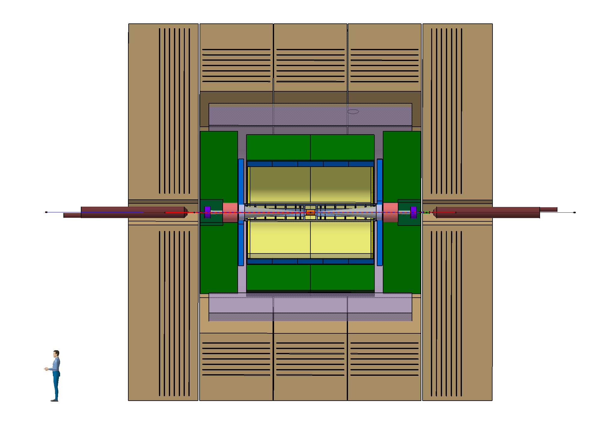
A cross-section of the overall layout is represented in the figure below.
For the GLD concept, most information is obtained from the Detector Outline Document. It is well possible that some of the information is outdated: please let me know if you find any incorrect statements.
LDC simulation
Monte Carlo simulation of the interactions of particles with the different LDC sub-detectors is performed using a software package called Mokka . In this framework a sub-detector is completely defined by the following elements:
- the most important detector parameters (dimensions, materials, etc.) retained in the Mokka data base (a MySQL relational database hosted by Ecole Polytechnique, France). Adrian Vogel at DESY has provided a browser for inspection of the different sub-detector layouts in the geometry. The current default detector is labelled LDC01_05Sc.
- a geometry driver this is a piece of C++ code that queries the Mokka DB and instantiates the GEANT4 volumes for all detector elements. The version of the drivers for the silicon sub-detectors is listed in the browser . The source code for the drivers is part of the Mokka release.
Mokka provides a scalable geometry: some key parameters (i.e. the radius of the tracking volume) can be modified at will before the actual simulation job is started.
The SiLC collaboration ( more information ) is responsible for the definition and maintenance of these detector description for Monte Carlo production. The current implementation is provided by Valeri Saveliev.
For more information about the linear collider simulation and reconstruction software, follow this link .
Constraints
The innermost tracking volume to be instrumented with silicon devices is delimited by three elements:
- the outer radius of the vertex detector (6 cm in the LDC and GLD design) is the inner boundary in the central part of the detector.
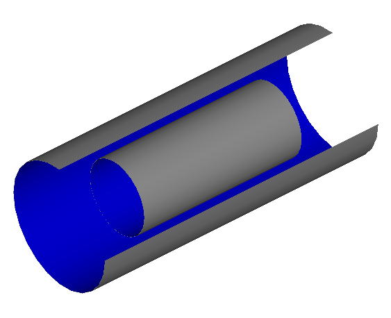
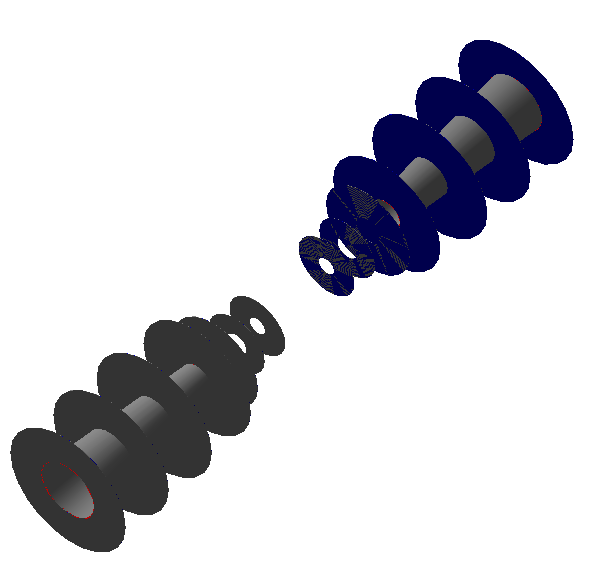
- moving to the forward direction, the conical beam pipe limits the inner radii of the forward tracking system (see figure below for the layout of the Forward Tracking Disks).
- the inner radius of the TPC yields an outer radius to both central inner tracker and forward inner tracker. The LDC' and GLD' layout envisaged the inner radius of the TPC enclosuere to be at 30.05 and 37.1 cm, respectively. The corresponding inner radius of the active TPC volume was foreseen to be 37.1 and 43.0, respectively.
The TPC radius is of crucial importance in the optimization of the inner tracking layout. Therefore, an overview of the arguments - from a thread in the ILD optimisation list - that go into the definition of this parameter is listed below:
"One of the driving forces behind the inner TPC radius has been
the outer radius of the Beam delivery system. The TPC is supposed
to slide over this, and this defines at least the minimal inner
radius of TPC. In fact, the number for LDC has been chosen in this
way. As you know, the layout of the BDS for ILD is under
discussion right now, and no final design exists quite yet. Maybe
at Sendai we will lean more and get more reliable numbers." (Ties Behnke). However, "In alternative opening scenarios this constraint may be reduced to just over the lumical acceptance" (Henri Videau). LumiCal in LDC01_05Sc extended from an inner radius of 80 mm to an outer radius of 195.2 mm (overriding the previous default value of 280 mm). Thus, it can be argued that the bare minimum inner radius derived from the detector opening constraints is roughly 20 cm.
Another constraint can be derived from "The minimal TPC radius wwhich can be tolerated from the point of view of background and positive ion flux." (Henri Videau). I have no feeling for what kind of radius is safe.... Suggestions are welcome.
A third argument when considering the minimal TPC inner radius is found in the forward tracking performance. A TPC of outer radius of 170 cm and a length of 200 cm is considered. A pad row width of 7.8 mm is considered (note that this is a more conservative assumption than keeping the number of pad rows constant). For the FTD and SIT layout the one in LDC01_05Sc is used. The inner radius of the TPC is varied, taking values of 20, 30 and 40 cm. SIT and FTD are simply squashed (all z-values remain the same, but the outer radii are scaled to match the varying TPC radius). The number of pad rows and FTD layers can now be counted as a function of polar angle.
20 cm 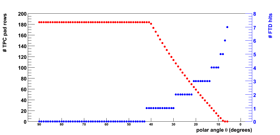
30 cm 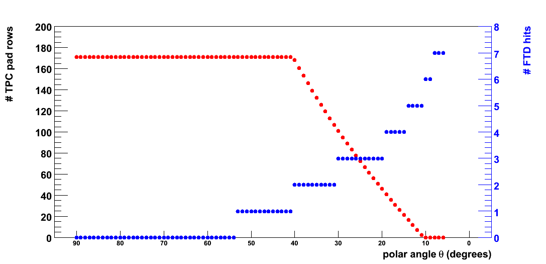
40 cm 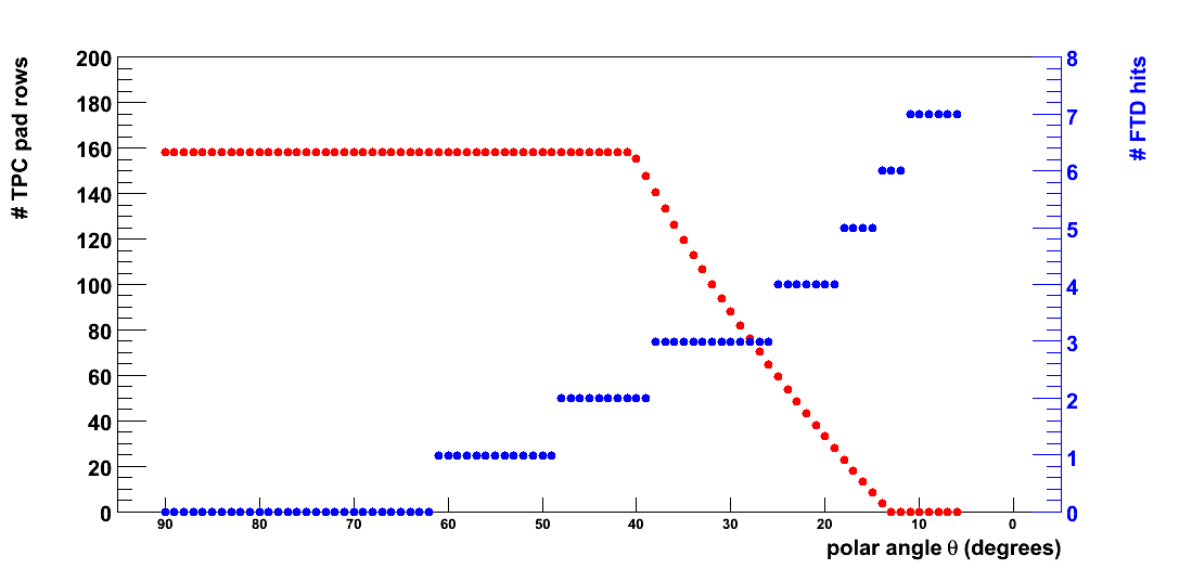
In the central region, tracks are reconstructed in the TPC alone, while in the very forward region tracks are reconstructed using the seven FTD hits. In the transition region the TPC and FTD track stubs are connected to form a track. For shallow tracks this process is made more difficult due to the large amount of material and relatively long distance (both get scaled by 1/cos(#theta) with respect to a central track) that the track meets upon entry into the TPC. With increasing TPC radius the transition region moves to larger polar angle, thus improving the chances of the matching procedure. If we consider that we need 3 points in FTD to be able to reconstruct a track stub sufficiently cleanly, the number of pad rows in the TPC in the worst case is approximately 30 for a 20 cm inner radius, about 50 for 30 cm, and increases to 70 for a 40 cm inner radius. While only a full-simulation study can provide a quantitative estimate of the impact on pattern recognition, it is clear that the situation is much more comfortable for larger radii.
Sub-systems
Four sub-systems may be distinguished;
- the Central Inner Tracker proves precise space points in the central tracking volume at intermediate radii between the vertex detector and the TPC.
- the very forward tracker providing measurements for tracks emitted at low angles (< 30 degrees) with respect to the beam axis.
- the Endcap Tracker providing a precise measurement between the TPC end-plate and the face of the calorimeter
- the Silicon Envelope Tracker providing a precise space point at large radius between the TPC barrel and the calorimeter
Below, the default detector description - and possible alternatives - is described for each of these sub-systems:
Central Inner Tracker
The default Silicon Intermediate Tracker layout consists of two cylindrical "barrels" at radii of 160 and 300 mm. The half-lengths of the two cylinders are 380 and 660 mm, respectively. Each consists of 200 &mu m of silicon representing the active material, and a Carbon layer representing the passive material. The overall thickness per layer amounts to 0.5 % X0. Many thanks to Hengne Li from LAL for the initial implementation of the layout.
The counterpart of SIT in GLD is known as the Barrel Intermediate Tracker (BIT). It plays an even more important role than SIT, as in GLD the TPC inner radius in GLD is signficantly larger: 40-45 cm (both numbers are used alternately in the DOD) instead of 30 cm (as a caveat we should remark here that the definition of inner radius is subject to interpretation: "do we include the width of the TPC field cage?").
The baseline BIT design foresees four cylindrical layers at radii of 9, 16, 23 and 30 cm. The half-length of each cylinder increases with radius (reaching values of 18.5, 33, 47.5 and 62.0 cm, respectively). Each layer is equipped with double-sided micro-strip detectors, providing an R &phi resolution of 10 &mu m ( 50 &mu m pitch) and a Z-resolution of 50 &mu m (100 &mu m pitch).
From a comparison of the ideas within LDC and GLD about this detector, the principal unknowns are the number of layers (2-4) and the importance of
The central inner tracker (SIT or BIT) is to provide precise space points in the gap between VXD and TPC. The discussion of its properties therefore depends critically on the size of this gap (i.e. the TPC inner radius).
The role of the space points provided by the central inner tracker is threefold:
The precise R &phi measurements - especially the last layer before the entry into the TPC - lead to a significant improvement of the transverse momentum resolution. The benchmark for this aspect of the detector performance is the Higgsstrahlung recoil mass analysis.
The space points provided by the central inner tracker are of great importance in pattern recognition, as they guide the connection of the track stubs reconstructed in the TPC and VXD. The beam-induced e+ e- background is much reduced with respect to the VXD. In this clean environment ambiguities that occur in the dense VXD may be resolved. These space points are especially important for non-prompt tracks that originate at a radius beyond the (first layers of) the vertex detector. Pattern recognition requirements drive the need for Z-segmentation of this detector. Benchmarks are non-prompt tracks (single K0), particularly if in a dense environment (b-jets).
The central inner tracker layers may be used to time-stamp the tracks. Classical micro-strip detectors typically identify a single bunch crossing from which they originate. For sufficiently energetic tracks, the combination of a silicon track (unambiguous z-coordenate) with a TPC track (excellent z/time resolution) provides a very precise time stamp. For low-momentum tracks, the combination of central inner tracker and forward silicon tracking must provide such a time-stamp.
The global detector performance relies heavily on a tight control of the overall tracker material. This is particularly true for electromagnetic calorimetry (photons, electrons). The impact of the tracker material on particle flow jet energy measurement is to be established.
Forward Inner Tracking
The default LDC has two times seven Forward Tracking Disks for tracking of low-angle charge particles. The whole system is mirror-symmetric in the origin, i.e. the +z and -z sides are identical.
| disk number | 1 | 2 | 3 | 4 | 5 | 6 | 7 |
| z position (mm) | 220 | 350 | 500 | 850 | 1200 | 1550 | 1900 |
| inner radius (mm) | 29 | 32 | 35 | 51 | 72 | 93 | 113 |
| outer radius (mm) | 140 | 210 | 270 | 290 | 290 | 290 | 290 |
Note that this layout extends to the full length of the TPC, ie to much larger z-values than the Forward Tracking Disks foreseen in the Tesla design.
The detector consists furthermore of an inner and outer support cylinder made up of passive material.
Several detector technology options are considered for the FTD. The outermost disks are envisaged to be equipped with (possibly double-sided) silicon micro-strip detector. Therefore, disks 4 through 7 are simulated as 300 &mu m of silicon active material. The innermost disks are to be equipped with more granular pixel detectors. Two options are available. The default technology, monolithic active pixel detectors (MAPs, DEPFETs, CCD) are taken to contribute 0.2 % X0/disk (200 &mu m of silicon). The backup option, hybrid pixel detectors, are represented as 300 &mu m of silicon and a carbon layer to make up a total of 1 % X0/disk. The two choices are available as ftd03 and ftd03a, respectively.
The Super-driver for FTD accepts one parameter: the TUBE_opening_angle taking into account the angle of the beam pipes with respect to the nominal z-axis.
The GLD concepts foresees a Forward Inner Tracker (FIT). With respect to the FTD design in LDC, several important differences are observed:
\begin{itemize}
\item the seven FIT disks extend to a z-value of 101.5 cm. Thus, FIT is considerably shorter than the GLD TPC (with a half-z of 200 cm).
\item the FIT disks should be equipped with (double-sided) micro-strip detectors, whereas for FTD a combination of pixel and strip detectors is envisaged
\item FIT disks provide an R &phi resolution of 25 &mu m, while FTD aims for a significantly better resolution ( 5-10 &mu m).
\end{itemize}
The forward silicon tracker is to provide essentially standalone track reconstruction for very low-angle tracks (5-15o), where VXD and TPC have very limited coverage. Several performance aspects are distinguished:
Vertex resolution: for tracks beyond the VXD coverage (5-10o) the innermost measurement is provided by the first, or even the second, forward tracking disk. Extrapolation to the beam line - over 15-20 cm - yields an impact parameter measurement with sensitivity to the B-hadron lifetime only if the first disks provide a precise space point and very little material. A further critical parameter is the amount of material in the VXD services that shadows the first tracking disks. A benchmark currently under investigation is the forward backward asymmetry in bb and cc production.
Momentum resolution: the momentum resolution in the very forward tracker is inevitably degraded (with respect to the performance of the central tracker) by the orientation of the (essentially) solenoidal magnetic field. To minimize the loss in performance, excellent R &phi resolution and the longest possible lever arm are essential. For low momentum tracks, the material budget plays an important role as well. The traditional benchmark (Higgsstrahlung recoil mass) for the central tracker does not provide much of a constraint for the forward tracker as a whole (the innermost disks ARE important to connect VXD and TPC). The most challenging benchmark is probably the center-of-mass energy determination using e+ e- -> &mu + &mu -.
Pattern recognition: the reconstruction of the abundant low-momentum tracks in the very forward tracker presents a considerable challenge. For low-angle tracks the seven available space points should provide sufficient constraints on the track model for the ambiguities in hit assignment to be resolved (compare the central tracker, with five high-granularity VXD measurements, 2-4 central inner tracker points and 100+ TPC measurements). Dense final states like e- -> qq (tt) have been studied in the past, establishing the the requirements for R-segmentation.
Time stamp: the outermost tracking disks should provide an unambiguous bunch crossing ID. For the innermost disks, the combination with the TPC yields a precise time measurement. As for the Central Inner Tracker, the time-stamping performance should be verified on real physics topologies.
Global detector performance requires the material budget to be constrained as much as possible. Many benchmark channels that particularly strain the forward region exist: selectron production (with the sensitivity of electrons on the detector material), W+ W- scattering (forward particle flow).
Endcap Tracker Disks
In both LDC and GLD, a silicon-based detector is envisaged between the TPC end-plate and the face of the ECAL endcap.
Needless to say, the z-location and radius of this device is intimately linked to the overall tracker radius and aspect ratio.
The number of envisaged layers (and the space available for them) differs between LDC and GLD (a single XUV disk in LDC, several layers in GLD).
The ETD provides a precise space point with a large lever arm and thus improves the momentum resolution for charged particles. The (effective) R &phi resolution is the most important detector parameter. As this detector is between central and very forward regions, benchmarks mentioned for both these systems are relevant (Higgs-strahlung recoil mass analysis, center-of-mass energy determination).
The ETD layer is moreover instrumental in "recovering" from the material effects that particles suffer in the TPC end-plate (estimates of the material in read-out electronics and supports vary from 15 % X0 to 30 % X0. For charged particles, this leads to significant multiple scattering. As the total distance between the active TPC volume and the face of the calorimeter is quite significant, thus spoiling the prediction of the track position on the calorimeter. Conversions and nuclear interactions have a potentially large impact on the particle flow. The measurement of a precise entry point for charged particles may greatly improve the assignment of charged particle calorimeter clusters to the tracks. Quantitative results should be obtained using an analysis of the particle flow performance.
Silicon Envelope Tracker
The Silicon Envelope Tracker layer is situated between the TPC barrel and the central calorimeter. It thus provides a precise space point (R &phi measurement) at large lever arm, instrumental to reach the ultimate transverse momentum resolution for high momentum tracks.
In the LDC DOD, the option of an additional silicon measurement beyond the outer radius of the TPC barrel is considered. In the GLD detector outline document, no mention of this Silicon Envelope Tracker is found.
The relevant benchmarkfor the momentum resolution is the Higgs-strahlung recoil mass analysis. The impact of the material will have to be evaluated by an analysis of the global detector performance: electrons/photons, particle flow jet energy measurement.
| 