
MODULE TEST - Setup
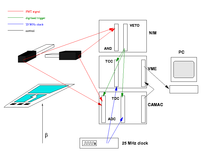
A schematic view of the setup is shown below:

As mentioned, the tests consist in determining the response of each
channel of the module to irradiation by 0.5-3 MeV Beta rays from a Strontium
90 source. The electrons, after traversing the silicon, are detected in
two 'finger' detectors of scintillating material, read out by photomultipliers.
The NIM logic generates a trigger on the basis of the PMT signals.
Besides, a copy of the signal is sent to the CAMAC ADC and TDC modules,
where the pulses are digitized (ADC) and the phase of the signal with respect
to the 40 MHz system clock is determined(TDC). This information is
used in the analysis to determine the trigger quality and discard events
that have intrinsic low efficiency.
A set of X-Y stages, controlled by the PC across a GPIB interface, allows
for the scanning of the source over the entire sensitive surface of the
module. The position information can be written into the data, in order
to reconstruct the hit/position correlation.
The module is read and controlled by the Irvine
DSP/LL/TCC VME modules. The TCC card takes care of synchronising and delaying
the random triggers before being sent to the chips on the module. The DSP
and LL card are used to control the chip parameters and receive and buffer
the data.
Finally, the setup contains a Bias Card to provide the bias voltage
of the chips and detector.
The VME and CAMAC busses are controlled by a PC running Linux, across
a Bit3 PCI-VME interface card, in such a way that the PC serves as VME
bus controller. The CAMAC bus is controlled by an VME-CAMAC interface.
The programme running on the host is the UCI CALRUN code, adapted to X11,
and with patches by Valencia (documented here), in order to support the
TCC, ABCD modules and the Bias Card 96. An important change is the data
format: the hit map of every event is saved in a Column Wise Ntuple, together
with the trigger data from CAMAC (two ADCs and a TDC channel) and the relevant
parameters in case of a loop over the chip settings. This method allows
a more profound offline analysis of the data.
Module test
Last Updated November 18, 1998
(silicio@ific.uv.es)
© IFIC 1998
