INTRODUCTION
First of all, it is explained the working mode of the stages from Naples Coombe Ltd. The stepper motors carry on with the movement of the stages, which is commanded by the DMC-1500 controller from Galil Motion Control, Inc.
The communication with the stages is going to be accomplished through a program developed in LabVIEW 4.1, that interact with the controller, the one which finally command the movement of the stages.
Before starting with the description of how the program works, has to be defined the specifications of the stages that are going to be used.
STAGES
There are eight stages, named from "A" to "H".
Six of these stages (A, B, C, D, F, and G) have a linear displacement, while the movement of the others two stages (E y H) is circular.
Stages A & B related to the biggest axis of displacement, stage A is the one of the bottom of the system while B is on top of it and moves perpendicular.
Stages C & F, in the other hand, belong to the smaller package of stages and have on top of them and with a movement perpendicular to them, stages D &G.
Finally on top of the system is located two circular axis E y H defining the complete equipment for the assembly.
All of the six linear displacement stages (A, B, C, D, F, G) have limits for the forward and reverse displacement, named as Forward Limit & Reverse Limit, that won’t be able to overpass. These limits are defined by the placement of magnetic switches, located along the axis of displacement.
Moreover, all the eight axis have also defined a point in their displacement, called Home position where the absolute position of every one of them it’s equal to zero. This position is fixed by using another magnetic switch also located along the axis of displacement.
The user can modify the position of the magnetic switches, by manually moving the switch to a new position.
The sign of the displacement for each one of the eight axes is shown in the following chart:
|
Axis |
Sign of the displ. towards axis motor |
Circular displacement from Home |
Conversion mm/steps Degree/steps |
Accuracy |
|
A |
Negative Value |
500 |
2 micron |
|
|
B |
Negative Value |
500 |
2 micron |
|
|
C |
Negative Value |
2000 |
1 micron |
|
|
D |
Negative Value |
2000 |
1 micron |
|
|
E |
Clockwise + Anti-clockwise - |
1000 |
10-3degrees |
|
|
F |
Negative Value |
2000 |
1 micron |
|
|
G |
Negative Value |
2000 |
1 micron |
|
|
H |
Clockwise - Anti-clockwise + |
1000 |
10-3degrees |
TABLE I: Axis characteristics.
Description of the LabVIEW programs.
Control Box is the name of the program developed under LabVIEW that is going to be used for doing the displacements of all the axis.
By clicking on the Control Box icon, two Front Panels appear, Control Box.vi and Position.vi. The first one is used to command the stages, establishing controlled movements and displacements, from the second Front Panel can be read in mm, the displacements that have been previously ordered.
N.B: In LabVIEW every program has a Front panel, the user interface where commands are ordered and a hidden Block Diagram which contains the code of the program.
All the displays shown at this document are Front Panels.
CONTROL BOX.vi
That's the main "VI"(Virtual Instrument), the one in which the user will act.

On top of the Front Panel there is a button with an arrow in it, called Run Button, that starts the program once has been defined the action to do.
Control Box has the following items:
It’s and horizontally displacement bar with a cursor, were can be done the selection of the axis to move.

This selection can be carried on in the following ways:
![]()
This indicator shows to the user the command that it’s in this moment acting. When the system is not running, "Stopped" command appears into the message window of the command.
When the user runs the program, the command shown in this message window changes and is replaced by another related with the selected button for the movement.
For the user it’s mainly an informative display, but for internal use of the program these commands are the ones that tell to the system which movement option has been selected, allowing the program to execute it.
![]()
With this control, the user sets up the velocity profile that it’s going to use for the specified displacement. In order to select one of the different options, the user has to press the black arrows beside the display, and all the different velocity profiles will appear sequentially.
The velocity units are steps/second and each one has a specific acceleration and deceleration rate.
When the user runs the program the "Slow" speed is set as the default working speed.
The top velocity (maximum value of velocity) for these motors is 2.000.000 steps/second.
There are four velocity profile options available:
|
A |
B |
C |
D |
E |
F |
G |
H |
|
|
Step Speed |
2 |
2 |
2 |
2 |
2 |
2 |
2 |
2 |
|
A |
B |
C |
D |
E |
F |
G |
H |
|
|
Slow Speed |
50 |
50 |
200 |
200 |
100 |
100 |
200 |
100 |
|
A |
B |
C |
D |
E |
F |
G |
H |
|
|
Medium speed |
500 |
500 |
2.000 |
2.000 |
1.000 |
2.000 |
2.000 |
1.000 |
|
A |
B |
C |
D |
E |
F |
G |
H |
|
|
Fast Speed |
2.500 |
2.500 |
5.000 |
5.000 |
5.000 |
5.000 |
5.000 |
5.000 |
![]()
This indicator shows a numeric value related with the detected error. It appears automatically in the window display and it’s the way that the program has to communicate with the user and advise him about any trouble that could appear while running.
As an example of that there are shown below some numbers and its related errors:
Number 0 means that every thing works properly
Number 2 means that the Forward Limit has been reached.
Number 4 means that the Reverse Limit has been reached.
Number 16 means that has been pressed the Master Stop button (See section "Operating Mode").
![]()
With this control the user can set displacements based on absolute coordinates.
Absolute coordinates: are those coordinates related to an absolute zero position point.
The absolute zero position point is defined for each axis by the location of their own Home Axis switches.
For the linear displacement of the stages, has to be used the same sign criteria as defined previously. The value introduced by the user has to be equal to the distance from the absolute zero position of the stage to the point that has to be reached (in mm).
![]()
For each stage has been defined a point in the displacement as the starting point. At this point the absolute coordinate value is equal to zero.
You can automatically place the stage over that position, by pressing the button labeled as "Home Axis" that appears at the Control Box Front Panel, and following the steps that later on will be described at the "Operating Mode" section.
![]()
With this control the user can set displacements based on relative coordinates.
Relative coordinates: are those coordinates related to the last reached position.
The value introduced by the user is equal to the displacement in mm desired for the selected stage.
For the linear displacement of the stages, has to be used the same sign criteria as defined previously.
![]()
With this control the user can set a continuos movement by pressing continuously with the left hand button of the mouse, over the REV button or the FWD button (depending of the desired displacement direction) that will appear in a new window (Jog.vi) that will be later on discussed.
This "Jog.vi" window appears automatically when the user runs the "Control Box.vi" after pressing the Jog button control.
This option of motion is useful for approaching the system to a desired area and in general for every kind of displacements that doesn’t need to be commanded by coordinates.
![]()
When the desired displacement of the stage has been accomplished, the stage stops its movement, but the program is still running, checking for errors and also ready for the introduction and execution of news commands.
The function of this button is stopping the program execution; if any further movement has to be commanded it would be necessary to run the program again.
This button does NOT allow stopping the movement of the stage once it began.
POSITION.vi
This second Front Panel shows in absolute coordinates and for each stage, their displacements from their Home Positions.
Once has been established a displacement for a stage, using the Control Box front panel, and begin to run the program, POSITION.vi shows in the display related with this stage the variations of it’s position.

POSITION.vi has a different window for each stage (at the left hand side of the front panel) and close to them there is a set of light indicators, one for each stage, that lights when a stage reach the Reverse Limit, the Forward Limit or the Home Position.
If the system has also encoders there is on the right hand corner of this Front Panel, a display showing its values.
By moving the bottom scroll bar towards the right hand side (when the system is not running) appears a set of eight numeric indicators labeled "Positions counts" where are shown the counts traveled by the motor during function. Any movement of the stage means a variation of its counts at a rate shown previously at Table I.
At Home Position the count values are equal to zero for all the axis.
OPERATING MODE
The routine that has to be followed in order to command a displacement of any stage using the Control Box front panel is now described:


Moreover when the execution of the program starts, appears a red button, titled "STOP".
This button is known as "Master Stop".
The purpose of it is to Stop immediately any movement that could have been ordered by the user, and actually in execution.

It’s a security button that stops the movement of the stage and abort, at the same time, the execution of the program.
Before start working, please read carefully the instructions related with the selected option of motion:
With this option is not necessary to fix previously the velocity of displacement of the stage.
Choose in the axis selector the stage that is going to be moved, as it was previously described. (See description of Control Box).
Press the Home axis button and after that press the Run button; the selected stage will start a movement that will finish at Home, and at this point the position counts indicator and the mm indicator of that stage will be automatically set to zero.
Stop the program by clicking the "Quit" button that appears at the Control Box.vi Front panel.
Choose in the axis selector the stage that is going to be moved, as it was previously described. (See description of Control Box).
Set the displacement speed, by clicking the arrow placed nearby the speed display indicator until that appears in it the desired one.
Set in the display of the selected option, the displacement in millimeters (in absolute or relative coordinates, depending of the chosen option) that has to be done:
![]()
If, as an example, the user sets a value of 10mm in the display, the stage will move to the 10 mm in absolute coordinates
![]()
If, as an example, the user sets a value of 10mm in the display, the stage will move 10 mm from the actual position.
Press now the command button, Move Absolute or Move Relative as desired.
At Position.vi will appear the new position values (in mm) that have been reached.
Stop the program by pressing the "Quit" button that appears at the Control Box.vi front panel.
Press the Jog button.
It will appear a new front panel titled "Jog.vi":

This is a new front panel, so the selected axis and the speed defined at Control Box.vi Front panel, velocity and selected axis, have to be reestablished before running it.
In order to do that:
![]()
It appears the same display that was at Control Box.vi, where to set the displacement speed as it was previously done.
There are two options:

If activated (the box close to the legend is filled with a cross), at the axis selector the cursor will be placed on the axis selected by Joystick.
The routine to be followed if the user wants to select the axis from the Front panel is now described:
A) If the "Use Jog Box" command is activated, first of all disconnect it by placing the pointer of the mouse over the white square close to the legend and pressing on it with the left-hand side button of the mouse.
Go now to the axis selector and choose the desired one as previously explained. B) If the "Use Jog Box" command is not activated select the desired axis by using the axis selector.
![]()
Over the axis selector there is a dialog window through which the controller communicates with the user, showing a message if any limit is reached.

This box has three buttons that command the axis movement. The two first one will move the stage in opposite direction, whilst the third one (Jog Stop) will close the Jog.vi Front panel.
In order to move a stage in a direction, place the pointer of the mouse over the button that is going to be used, FWD for displacements on the Forward direction (positive values of the stage) and REV for displacements on the Backward direction (negative values of the stage) and keep on pressing it until the desired position has been reached.
Press the "Jog Stop" button to close the Jog.vi Front panel and return to the Control Box Front panel.
Stop the program by pressing the "Quit" button that appears at the Control Box.vi Front panel.
ADITIONAL NOTES:
NOTE 1:
If while working it would be necessary to order and command several actions, instead of pressing the "Quit" button after the end of each one of them, the user, once one order has been done, can directly set a new one and the program will execute it immediately without pressing the run button again.
After chaining all the desired movements, stop the program by pressing the "Quit" button that appears at the Control Box.vi Front panel.
NOTE 2:
There is a file called Position.dat where the system keeps the value in counts of the latest reached position for each one of the eight stages of the system.
That's the unique way the system has to know where it is, and each time the user run it goes to this file and read the position of its stages.
If any movement is done without using the Control Box.vi, the reached position will no be stored in this file and later on when the user run the program again, the values in counts and millimeters taken from Position.dat, will not be the correct ones.
When the user install the software for the first time, has to take the Position.dat file provided at Web site and place it with the LabVIEW libraries (LVDMC3_2 & UtilVDMC.llb) into the file LV_DMC which its also placed into a bigger directory file called Assembly, because is there where the program will look for it.
The count values that contains this document are not valid for the user system, so the way to proceed is to place all the stages at its home position (by using the Home button), and arriving there the counts will be automatically set to zero; from now in advance, the counts and millimeters values will be the correct ones for the user system.
NOTE 3:
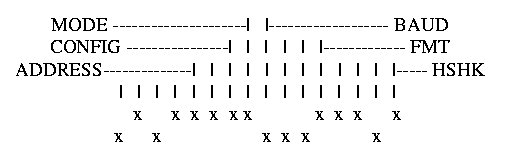
Finally it's shown the configuration of the switches of the Galil controller.
The DMC-1500 controller has two RS232 ports the main one and the auxiliary one. The main port can be configured through the switches on the front panel and the auxiliary port can be configured with the software command CC.
The switches from the front panel have to be placed according to the table below:

With this configuration, the baud rate is the maximum one (38400) between the Controller and the GPIB-232CV to enable rapid updates of position and switch conditions.
And on the GPIB-232CV-A as follows: